Image credits: Srinivasan Narasimham (CMU), Fredo Durand (MIT), Mark Levoy (Stanford), Ashok Veeraraghavan (Rice), Aswin Sankaranarayanan (CMU), and Kaushik Mitra (IITM).
The images are purely used for academic purposes. The copyright belongs to the owner.
Basics of Imaging
Image Formation
The world is made up of different types of materials. Each material has its intrinsic properties that tells what wavelengths of light will be absorbed or reflected by the material. What we see through our eyes is a bunch of wavelengths of light reflected by materials. We perceive these wavelengths in the form of, what we call as colour. In a camera, we intend to capture and store the light of the world for later use. Our primary aim is to capture light that we see (that is, visible light), though in many applications, we capture light information in various other forms different from that of a human eye.
To detect light, we need a photosensitive material. This material produces electricity when photons of the light are impinged upon them. The amount of electricity produced depends on the amount of photons that are hit. Dark objects which reflect few photons produce lesser electricity than bright objects. Through this change in the produced electricity, we can store how much photons are travelling through a particular point in the space.
To record colours, we filter the light so that we capture photons that are only in the visible part of the light spectrum. Further, various colour filters are used to detect particular colours. We will stop here about the basics of light, and we go into studying the camera models that helps us to capture light in a focused manner.
Pinhole camera
Pinhole is the basic camera model in imaging. The aperture through which the camera sees the scene is a pinhole, i.e. a very small aperture of infinitesimal size. The light from the scene enters into the pinhole and gets recorded in a photosensitive medium. The light recorded is upside down and flipped, but this can be rectified by a simple geometric operation while viewing the image. Below is an illustration of a pinhole camera.

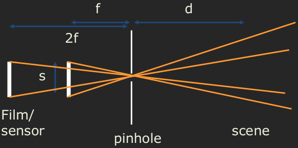
The ray diagram of a pinhole camera is given below. There is a sensor present inside the camera at a distance \(f\) from the pinhole, and this distance \(f\) is called the focal length. The variable \(d\) represents the distance of an object in the scene to the pinhole. The light from the scene is recorded at the sensor, which a two dimensional plane formed using a photosensitive medium. The size of the sensor is given by \(s\).

Field of view
The field of view of the camera is the cone of light that enters the pinhole. In the 2D ray diagram, the cone is a triangle. Though a cone of light enters the camera, the image recorded is a rectangle. Hence in practical cases, the cone is actually a pyramid. The field of view determines the bounding box in the scene that gets recorded in the sensor. At different distances \(d\), bounding boxes in the scene vary. At small \(d\), the area covered is small, while for large \(d\), this area is large. At a fixed distance \(d\), the field of view is controlled by the focal length of the camera. As shown in the following figure, doubling the focal length decreases the field of view (by what amount?).
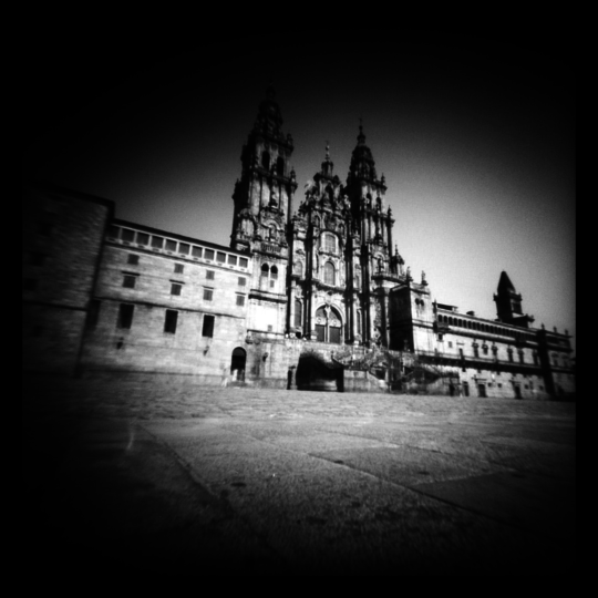
Below three images are taken with different focal lengths. Note the change in their respective fields of view.

Vignetting
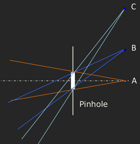
Vignetting (pronounced vin-net-ting) is a common effect or an artifact in pinhole cameras. This is caused by the decrease in the volume of the cone as we go near the edges of the bounding boxes in the field of view at a particular distance. Consider the three points \(A,B\) and \(C\) which are the same distance from the camera in the diagram below. Observe their respective cones of light. The point \(A\) has a large cone volume, next comes point \(B\), with \(C\) contributing with the smallest cone of light. Hence, while recording the image with a particular exposure time, \(A\) contributes more light, followed by \(B\) and \(C\). This difference in light contribution rises to the vignetting effect as shown in the image below.
Aperture size
A question to be asked is how small or large is a practical pinhole. Can we go as small as possible? How large can we go? If we increase the aperture, we can see that a blurring effect is produced in the image. Observe the following image.
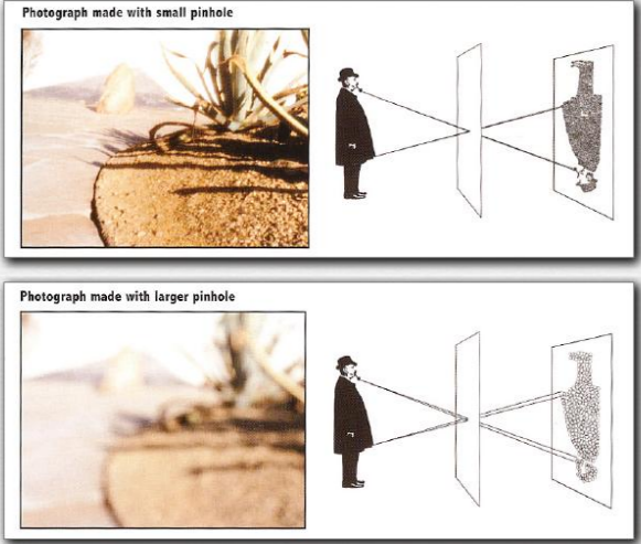
This is due to the spread-out of rays at the aperture. The light from a single point in the scene spreads out to a circle at the sensor. This creates blur that depends on the distance of the object from the aperture. Closer objects creates larger blur (is this right?).
If increasing the aperture will cause blur, why not we reduce the aperture to an infinitesimal size? Then, there will not any issue of blurring! Nope. Small aperture beyond a certain size causes diffraction of rays due to the wave nature of light. This too causes blur!

The issues with the pinhole camera in practice leads to lens-based imaging. In place of a pinhole (empty) aperture, we use a lens which focuses the scene onto the sensor plane to create an image. The term focal length which we used in the pinhole model is borrowed from lens-based imaging indeed, because only the lens focuses.
Lens camera
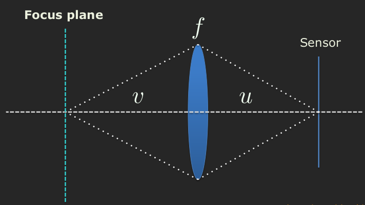
The struture of a lens camera is similar to that of a pinhole one. We have a sensor plane at a distance \(u\) from the aperture. The aperture is not an empty hole here, but a physical lens. The lens focuses only a plane of the scene onto the image depending on its focal length \(f\). This plane in the scene is called as focus plane. The distance of the focus plane from the lens is given by this lens law.
\begin{align} \frac{1}{f} = \frac{1}{u} + \frac{1}{v}. \end{align}
We will study about the lens camera properties, focal length, aperture, and exposure, in the next section.